

Achieving good impedance matching for a Waveguide Rotary Joint is crucial for the efficient operation of microwave and millimeter - wave systems. As a Waveguide Rotary Joint supplier, I have witnessed firsthand the importance of this aspect in various applications, from radar systems to satellite communications. In this blog, I will share some insights on how to achieve good impedance matching for a Waveguide Rotary Joint.

Understanding Impedance Matching
Before delving into the methods of achieving impedance matching, it is essential to understand what impedance matching means. In a waveguide system, impedance refers to the ratio of the electric field to the magnetic field. When the impedance of the source, the load, and the transmission line (in this case, the waveguide) are the same, maximum power transfer occurs, and reflections are minimized. This is known as impedance matching.
Poor impedance matching can lead to several issues, such as signal loss, reduced system efficiency, and interference. For a Waveguide Rotary Joint, which allows for rotational movement while transmitting electromagnetic waves, achieving good impedance matching becomes even more challenging due to the mechanical rotation and potential misalignments.
Factors Affecting Impedance Matching in Waveguide Rotary Joints
- Waveguide Dimensions: The dimensions of the waveguide, including the cross - sectional size and the length, play a significant role in determining its impedance. Any deviation from the standard dimensions can cause impedance mismatches. For example, if the width or height of the waveguide is slightly different from the design specifications, it can lead to reflections and power loss.
- Material Properties: The materials used in the waveguide and the rotary joint components can also affect impedance matching. Different materials have different dielectric constants and conductivity, which can change the propagation characteristics of the electromagnetic waves. For instance, a waveguide made of a material with a high dielectric loss will result in more power dissipation and potential impedance mismatches.
- Mechanical Alignment: The alignment of the two parts of the rotary joint is crucial. Even a small misalignment can cause significant impedance mismatches. During rotation, the mechanical parts may experience wear and tear, which can further affect the alignment and, consequently, the impedance matching.
- Frequency Range: The impedance of a waveguide rotary joint is frequency - dependent. Different frequencies have different propagation characteristics in the waveguide, and achieving good impedance matching over a wide frequency range can be particularly challenging.
Methods to Achieve Good Impedance Matching
1. Precise Design and Manufacturing
- Accurate Waveguide Dimensions: During the design phase, it is essential to calculate the waveguide dimensions accurately based on the desired frequency range and impedance. Advanced computer - aided design (CAD) tools can be used to simulate the electromagnetic behavior of the waveguide and optimize its dimensions. In the manufacturing process, high - precision machining techniques should be employed to ensure that the actual waveguide dimensions match the design specifications as closely as possible.
- Material Selection: Choose materials with stable dielectric properties and low losses. For example, copper is a commonly used material for waveguides due to its high conductivity. The surface finish of the waveguide also matters. A smooth surface can reduce losses and improve impedance matching.
2. Tuning Elements
- Stub Tuners: Stub tuners are short - circuited or open - circuited sections of waveguide that can be used to adjust the impedance. By placing stub tuners at appropriate locations along the waveguide, the impedance can be matched to the load impedance. The length and position of the stub tuners need to be carefully calculated based on the frequency and the impedance mismatch.
- Matching Transformer: A matching transformer can be used to transform the impedance of the source or the load to match the impedance of the waveguide. This can be achieved by using a tapered waveguide section or a multi - section transformer.
3. Mechanical Alignment and Maintenance
- Precision Assembly: During the assembly of the Waveguide Rotary Joint, precise alignment tools and techniques should be used to ensure that the two parts of the joint are properly aligned. This may involve using fixtures and alignment pins to guarantee accurate positioning.
- Regular Maintenance: Regular inspection and maintenance of the rotary joint are necessary to detect and correct any mechanical misalignments. Lubrication of the moving parts can also reduce wear and tear and maintain good alignment over time.
4. Testing and Calibration
- Impedance Measurement: Use specialized impedance measurement equipment, such as a vector network analyzer (VNA), to measure the impedance of the Waveguide Rotary Joint. This allows for the identification of any impedance mismatches and the adjustment of the tuning elements accordingly.
- Calibration: Calibrate the measurement equipment regularly to ensure accurate results. Calibration standards should be traceable to national or international standards.
Our Products and Their Impedance Matching Features
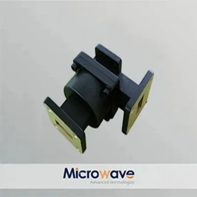
As a Waveguide Rotary Joint supplier, we offer a range of high - quality products designed to achieve excellent impedance matching. Our New Circular Waveguide Rotary Joint is engineered with precise dimensions and high - quality materials to minimize impedance mismatches. The circular design provides a more uniform electromagnetic field distribution, which is beneficial for impedance matching.
Our Waveguide Rotary Joint is available in various sizes and configurations to meet different application requirements. We use advanced manufacturing techniques to ensure that the waveguide dimensions are accurate, and the surface finish is smooth. This helps in achieving good impedance matching over a wide frequency range.
The L - Shaped Rotary Joint is another product in our portfolio. Its unique L - shaped design allows for more flexible installation in different systems. We have incorporated tuning elements in the design to optimize the impedance matching and reduce reflections.
Conclusion
Achieving good impedance matching for a Waveguide Rotary Joint is a complex but essential task. By understanding the factors that affect impedance matching and implementing the appropriate methods, such as precise design and manufacturing, the use of tuning elements, mechanical alignment and maintenance, and testing and calibration, it is possible to achieve excellent impedance matching and ensure the efficient operation of microwave and millimeter - wave systems.
If you are in need of high - quality Waveguide Rotary Joints with excellent impedance matching performance, we are here to help. Our team of experts can provide you with customized solutions based on your specific requirements. Contact us for more information and to start a procurement discussion.
References
- Pozar, D. M. (2011). Microwave Engineering. Wiley.
- Collin, R. E. (2001). Foundations for Microwave Engineering. Wiley.
- Jackson, J. D. (1999). Classical Electrodynamics. Wiley.