

Hey there! As a supplier of Ka Band Circulators, I often get asked about how these nifty devices work, especially the coupling mechanism. So, let's dive right in and break down the coupling mechanism in a Ka Band Circulator.
First off, what's a Ka Band Circulator? Well, it's a key component in microwave systems, operating in the Ka frequency band (26.5 - 40 GHz). These circulators are used to direct microwave signals in a specific order, typically in a circular pattern from one port to the next. They're super important in various applications like radar systems, satellite communication, and wireless networks.
Now, let's talk about the coupling mechanism. At its core, the coupling mechanism in a Ka Band Circulator is all about transferring electromagnetic energy between different parts of the device. It's like a well - choreographed dance where the energy moves smoothly from one port to another in a predefined sequence.
The basic structure of a Ka Band Circulator consists of a ferrite material placed in a magnetic field. Ferrite is a special type of ceramic material that has unique magnetic properties. When an electromagnetic wave enters the circulator through one port, the interaction between the ferrite and the magnetic field causes the wave to be coupled to the next port in the sequence.

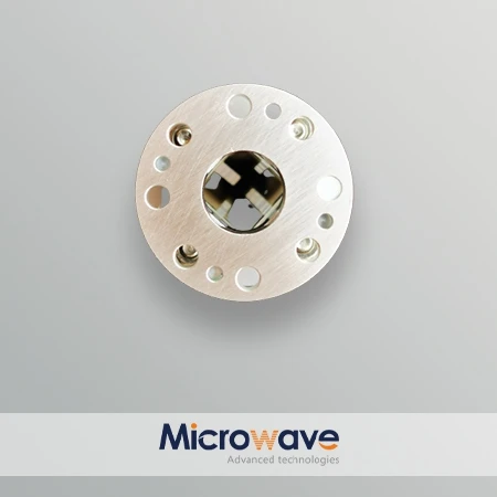
Let's take a closer look at the physical process. The magnetic field applied to the ferrite material creates a non - reciprocal behavior. Non - reciprocity means that the behavior of the device is different depending on the direction of the signal flow. In a circulator, this non - reciprocity is what allows the signal to travel in a specific circular path.
When a microwave signal enters the circulator, it excites the ferrite material. The ferrite's magnetic properties cause the polarization of the electromagnetic wave to change in a way that is dependent on the direction of the magnetic field. This change in polarization determines which port the signal will exit from.
Imagine you have a three - port Ka Band Circulator. If a signal enters at Port 1, due to the coupling mechanism, it will exit at Port 2. If the signal enters at Port 2, it will go to Port 3, and if it enters at Port 3, it will come out at Port 1. This sequential flow of signals is made possible by the coupling between the ferrite, the magnetic field, and the electromagnetic waves.
One of the key factors in the coupling mechanism is the proper design of the magnetic field. The strength and orientation of the magnetic field need to be precisely controlled. If the magnetic field is too weak, the coupling may not be strong enough, and the signal may not be properly directed to the next port. On the other hand, if the magnetic field is too strong, it can cause unwanted losses and distortion in the signal.
Another important aspect is the quality of the ferrite material. High - quality ferrite with consistent magnetic properties is crucial for efficient coupling. Any variations in the ferrite's composition or structure can affect the coupling mechanism and lead to performance degradation.
In practical applications, the coupling mechanism in a Ka Band Circulator also needs to be optimized for low insertion loss and high isolation. Insertion loss refers to the amount of signal power that is lost as the signal passes through the circulator. Low insertion loss is desirable because it means that more of the signal power is transmitted to the next stage of the system.
Isolation, on the other hand, is a measure of how well the circulator separates the signals between different ports. High isolation ensures that there is minimal interference between the input and output signals, which is essential for the proper functioning of the overall microwave system.
Now, let's talk about some of the real - world applications where the coupling mechanism in a Ka Band Circulator shines. In satellite communication, these circulators are used to separate the transmit and receive signals. The coupling mechanism allows the transmitted signal to be directed to the antenna while preventing it from interfering with the received signal.
In radar systems, Ka Band Circulators help in managing the flow of signals between the radar transmitter, receiver, and antenna. The precise coupling ensures that the radar can accurately detect and track targets without any signal interference.
If you're in the market for high - quality Ka Band Circulators, we've got you covered. Our circulators are designed with the latest technology to ensure optimal coupling and performance. We also offer other related products like the KU Band Waveguide Isolator 120W and the Waveguide To Coaxial Adapter WR75 Type. You can check out our Ka Band Circulator product page for more details.
Whether you're working on a small - scale research project or a large - scale industrial application, our Ka Band Circulators can meet your needs. If you're interested in purchasing or have any questions about the coupling mechanism or our products, don't hesitate to reach out. We're here to help you find the right solution for your microwave system.
References:
- Pozar, D. M. (2011). Microwave Engineering. Wiley.
- Collin, R. E. (2001). Foundations for Microwave Engineering. Wiley - Interscience.